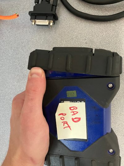
MDI-2 USB Port Replacement
BySteve Byrne, Certs
M.S. Candidate Information Technology,
B.S. Cyber Operations, Minor Computer Forensics
B.S. Fire Administration,
B.G.S. Technology & Mathematics, Health, Social Science,
A.S. Software Engineering,
A.S. Networking Security & Server Administration,
A.S. Fire Science,
Comptia Net+,
Comptia Sec+,
Nataionally Registered EMT-B,
MN Firefighter 1, 2, Hazmat Ops, Instructor 1,
AHA Advanced Cardiac Life Support,
AHA BLS Instructor,
Advanced Pediatrics Life Support,
List of Authored Research & Texts
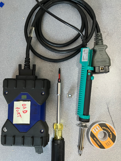
Section Zero: Tools & Equipment +
Minimum Required Tools / Equipment
1) Soldering Iron -- Preferably high temp with a small coned tip.
2) Solder -- Preferably rosen core Amazon Link.
3) T-10 Torx Bit Screw Driver/Bit Amazon Link.
4) New Compatible Port -- We'll be replacing the USB-B port Amazon Link.
Recommended Additional Required Tools
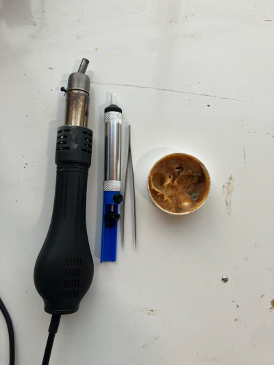
1) De-Soldering Iron -- Preferably A High Temp Iron, however A Suction Tool will work too!
2) Air Solder (Rework) -- Preferably small tip Amazon Link.
3) Flux Amazon Link.
4) Tweezers, Pick, or Small Prybar (Flat Head Screw Driver)
5) You (you're a tool)
Section 1: Disassembly+
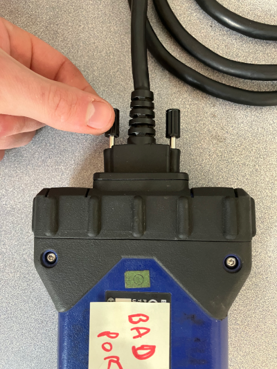
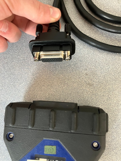
Step 1: Remove DLC Cable
Start by unscrewing the DLC cable, there are no tools required, just turn the knobs counter clockwise and pull back slightly until they are clearly free and move in and 1-2cm (1/4 bald eagles)
then pull back directly on the hard plastic part of the cable, don't just yank it by the cord. DLC cable and process shown below.
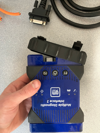
Step 2: Remove Rubber Ends
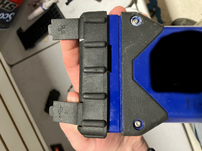
Next remove the rubber end caps by pushing your weak little fingers under the edges and forcing it off. Nothing holds these in place, just hit it with your purse if it doesn't slide off. As a tip, you can work on end and then the other as shown below.
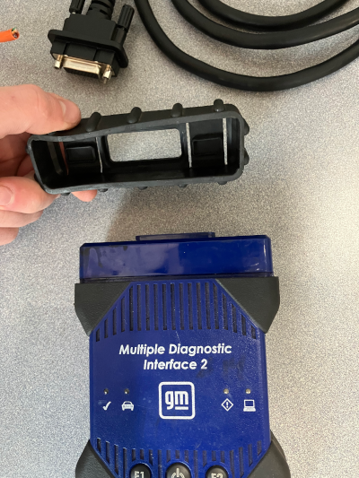
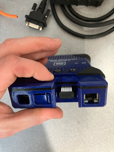
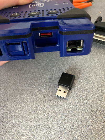
Step 3: Remove USB WIFI Dongle
Next remove the USB Wireless adapter card
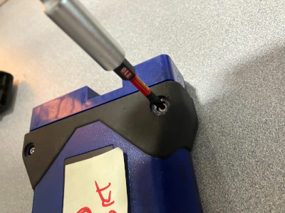
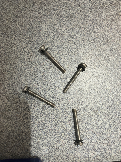
Step 4: Remove 4x T-10 Screws
Take your big boy screw driver and take out each of the 4x T-10 torx screws -- (I am working off the Gemini definition of a screw being turned to be inserted/fastened,
and a bolt having something turned around it while it remains stationary to fasten/secure it) --
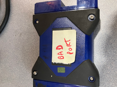
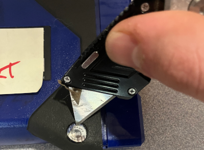
Optionally, use a heat gun and a fine pick or razor blade to heat the warranty sticker, slice under it, ensuring you cut just slightly into the plastic to leave the warranty glue intact, and remove the sticker. For scientific purposes only, removing that screw voids the warranty and you should never, ever try to lie about a warranty claim!
Note that each of these 4x scews have a washer on them and may not come all the way out without some gentle encuragement, try not to lose those washers.
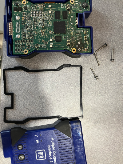
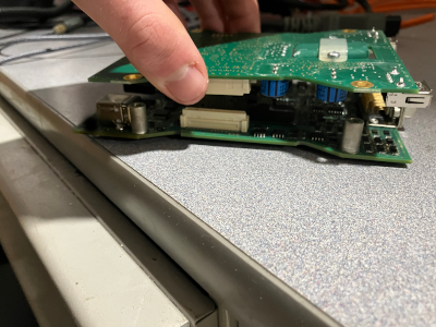
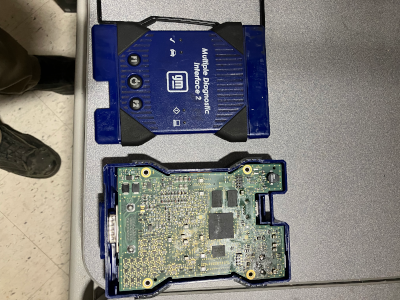
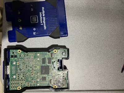
Step 5: Seperate The Boards
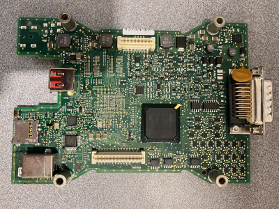
This is it, the moment you don't really care about! Slide the board out of the plastic housing (its actually two boards), you can also just tip it upside down and tap it a little, electronics are pretty strong, most of the time, probably.
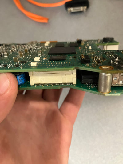
Pull straight down on the bottom board and straight up on the top board at the same time and the two boards will seperate, they are only held in by 2x multipin connectors (tan) on either side, shown below.
![Here [HEIC]](https://byrneworld.com/img/mdi2/Non-scaled/IMG_1680.HEIC)
Section 2: Desolder & Fit Dry Fit+
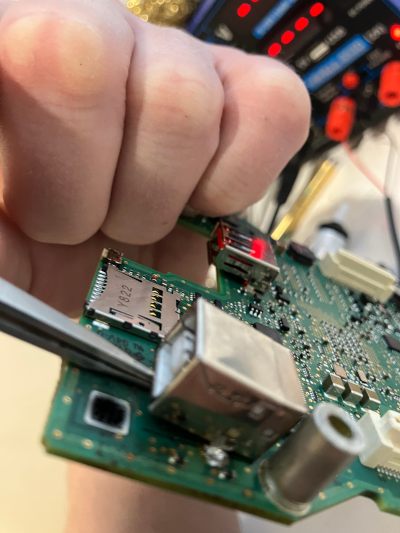
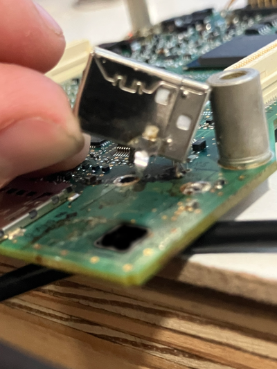
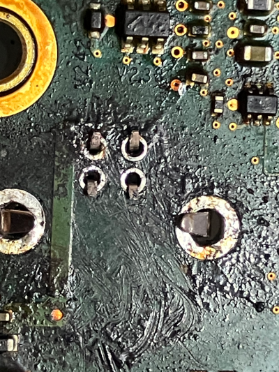
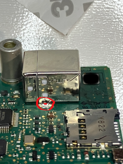
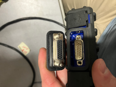
Step 1: Identify The Port
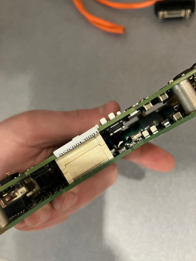
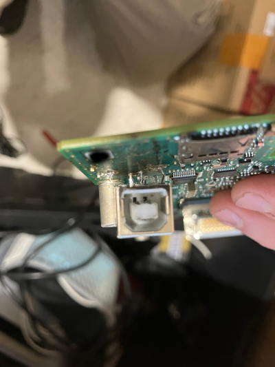
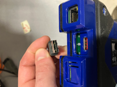
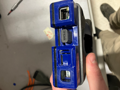
Go ahead and open up those two things on your head, no, stop sniffing, the other two... Great! Now find the broken port, it's probably wrecked and if it totally broke off, you might need to look around a bit for where it went. Below outlines some common ports on the board , normally we're replacing the USB-B (printer cable type port) as shown in the picture.
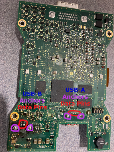
The USB-B 2.0 has 4 connection pins and 2 large anchor/ground pins. If you're thinking I should have called them earthing pins, go away.
The primary purpose of the large pins is to hold the port in place while the little pins actually handle the data. If you ahve the wrong port, like a USB-B 3.x port, you'll have more than 4 pins and will need to go get the right damn port.
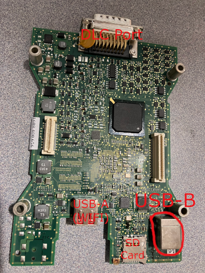
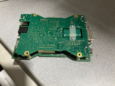
Full Size Images of Board Available Here | https://byrneworld.com/img/mdi2/Non-scaled/board/
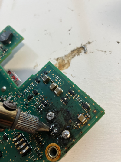
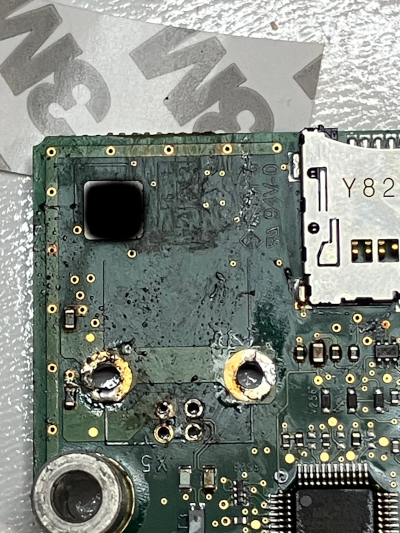
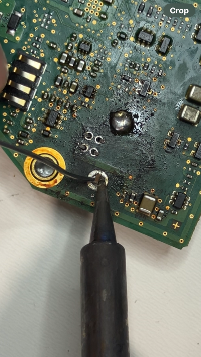
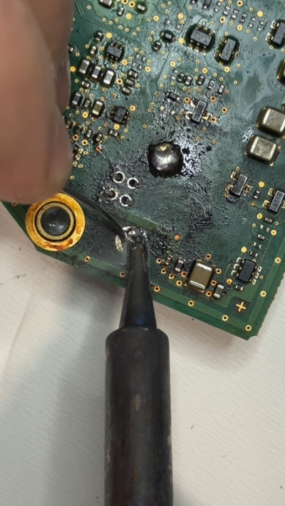
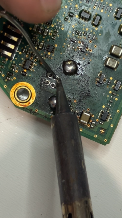
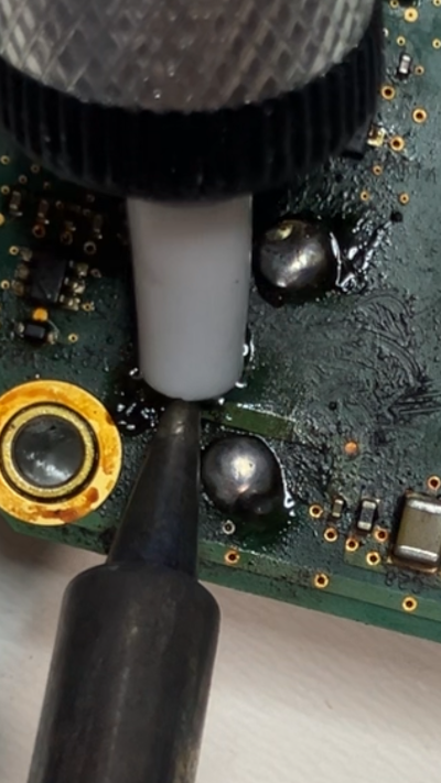
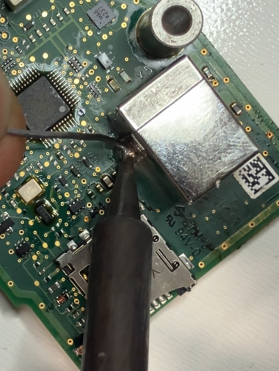
Step 2: Desolder The Port
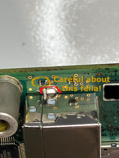
In a moment of seriousness, this is where you need to put away the hammer and grab the soldering tool. If the port broke off from the board you will have easier access, but also you still want to be sure to only heat up the things you're removing. Historically I've used a heat gun, and that runs a lot of rist for desoldering other components. Use the soldering iron or desoldering iron to heat the small pints first and remove the solder. If you didn't get a suction or desoldering iron, you're job is going to be really hard, you'll have to heat the pin and scoop it out with the soldering iron, likely rocking the pin back and forth to free it. Go around all 4 pins, heating the pins at or near the base. Once some of the larger areas are removed, heat the achors and start removing the bulk solder build up on them. Again, if you have a desoldering/suction tool, this is a pretty easy task, if not, you may have to get your pick or paper towels or something similar to scoop out 200-600(f) degree melted metal. The suction tools (including the desolder iron, which is just a soldering iron with a suction tool built in) is just a spring loaded button released vaccum that will pull the melted solder up into the chamber. Even if you do a perfect job, the port may not just fall out. Pins can be bent over the board (in fact, the should be in a lot of applications) so you may have to apply pressure with your tool (soldering iron, screw driver, tweezers, etc) under the port to pull it away from the board while you heat the pins. This is where if you have a heat gun, you can warm all the pins at the same time, super convient! However, pay extremely close attention to the heat radiating off. There are multiple capacitors close to the port's pins that can desolder easily and turn your MDI into a brick until they are replaced. Remember that warranty sticker? Yeah, this isn't covered under warranty. This is basically not risk with the iron, super high risk with the heat gun. Your call. Remember, electronics are pretty robust, you can apply modest pressure to the port while solding the pins out to get it out. The plastic hold the port's internals will break before the board does (that's how we get into this mess msot of the time) So just keep wiggling the port and removing as much solder as you can. The images below poorly outline how to do this, but hey, its hard to solder, pull, and take pictures with exactly 9 fingers.
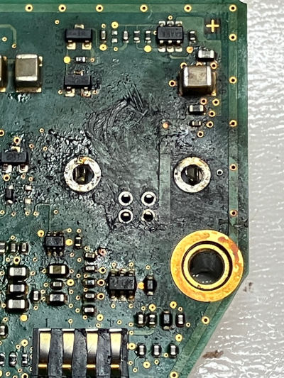
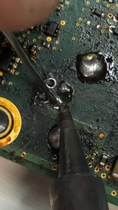
Step 3: Dry Fit & Resolder
The better job you did removing all the old solder, the easier this step will be. Pay attention to the pins on the new USB Port and line the little pins up with the 4 holes.
Push the port into the board, trying to angle the pins (which can be moved left and right a little bit) while still getting the anchors into the board opening. If you get the pins mostly lined up, at the anchors at least touch the hole, give it a good little steady constant pressure and it should work its way in.
Again, electronics are stronger than we give them credit for, but if the viens in your hand start popping out, maybe ease up a little... Wiggle and shake that thing more than your mom at the club in a sundress and and you'll feel a satisfying pop when you port goes in. Check the back, and take a look at back side of the port while you're back there.
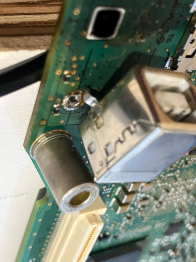
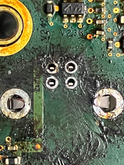
All 4 pins should be poking through the holes and the anchors should be through or close.
Use a pick (or the tip of you soldering iron) to bend the anchors out and down on the outside of the anchor holes to hold it in place.
Optionally, you can do this with the 4 data pins too (there are mixed opinions on this); if you do bend the pins make sure the back pins go back and the front pins go forward so they have no chance of touching each other.
Notable, the pins should all be roughly the same length through the baord, if one is longer or short, make damn sure its 1) stable, 2) the port is pressed flat against the board. Though not common unless you applied heat (like with an air solder) those pins can push up
into the softer plastic and break on the inside of the port, and then you're just practicing re-soldering a broken port.
With the dry fitment done, go ahead and solder the anchors first, from the bottom (we'll clean up the top side later). With the anchors pushed in on the board it should be fairly secured, but soldering the anchor will hold it place.
Whenever we solder, we don't heat the solder or the board directly, we heat the metal we're soldering to the board. IE, put the soldering iron on the achor's foot on one side, and place the solder on the opposite side.
If you place the solder on the soldering iron to get it to melt, you'll get what's called cold solder, which looks fine, but will transfer less data than your uncle's public defender during the discovery process.
Once done, move back to the data pins and heat near the base of the pin (near or touching the board). Its perfeclty fine, and actually better, to left the iron touch the orangish color circle around the pin, that's where we're going to be making contact so that area is also "the metal" we're soldering.
The larger the pin, the more thermal mass, the more thermal mass, the more heat required to melt the solder properly, that is, if you make good contact, the little pins will solder faster than the anchors. Keep in mind, its harder to get and keep sold contact with the smaller pins, so you might need to move around a little bit to get a good spot.
Additionally, if you just can't get the solder to melt, you can dap a little bit on the tool, the solder should be flux or rosen cored, which helps dissipate and distribute the heat. In fact, you can even sometimes add solder to help remove old solder.
Okay, each pin is soldered as shown in the images above and the bottom anchors are set, flip the board over like Jesus flipping tables in the temple, and add a little bit of solder to those top amchor points. Here we're not so worried about quality of solder, we're worried about
1) not having so much solder that it touches any other conducting surfaces, and
2) that there is enough around the port's anchors that it won't wiggle and slowly break over time,
mechanical advantage is a bitch. Pulling straight up on this port won't hurt it for years, but toss a 2-3" usb cable in there, press down and watch how fast a 3:1 snaps that port off like a panicked quarter back about to get sacked by Taylor Swift.
Step 4: Assembling Enough To Testing
Here's the deal, if you're confident in your job, you can just toss everything back together in the reverse order of the disaseembly, BUT, you came to this website, or print out, or, however you're reading this, which means you
probably needed a little guidance on making this happen, so let's test it before we put all those screws back in.
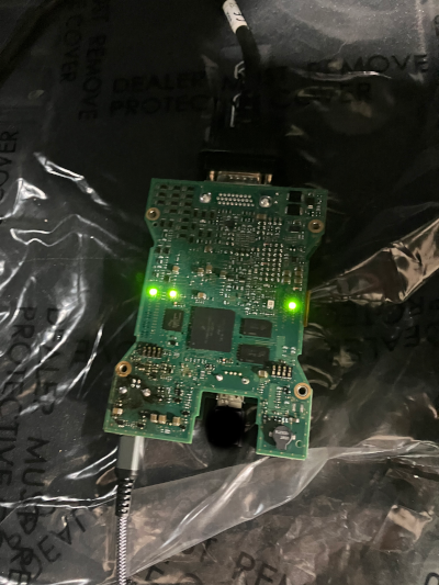
Put the two boards together and scew in your DLC cable, go over to a car (doesn't matter what kind), plug in your USB cable, and connect the cable to the computer (we're not in the car yet, just in case something goes.... Boom.)
Does the unit power up? Great! Does the computer recognize it is connected? If it says device unrecognized, one of your data pins (probably the sending pin/s) are not making good contact, if it doesn't see anything, the recieving pins aren't making a good connection
If this happens, re-solder the data pins and give it a couple more tries until you give up and compeltely remove it and install a new port, send it out for repairs (msg me, bby), or are smart and double check your computer's port is working and can see other MDIs, just in case you hecked up the drivers on it (honestly, pretty rare these days though).
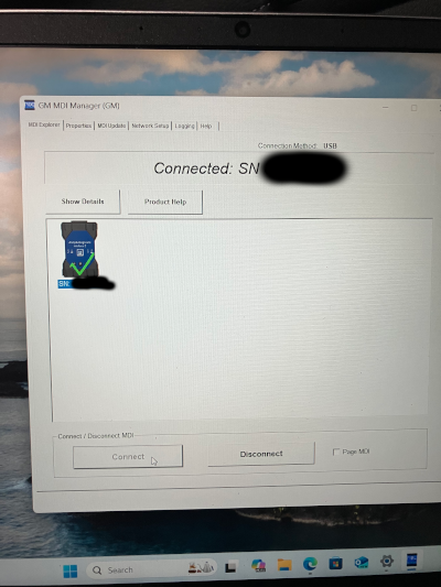
If the computer does recognize it, plug it into a car, doesn't matter if its GM/Chevy/Ford/or a freaking Crosley with an OBD2 port, we just have to see if data sends/receives. If your MDI software can connect to the device, all pins are working.
As a note, recent versions of TechLine Connection won't let you connect unless the DLC cable is plugged in, that may change in the future, we just have to make sure we can connect, even using MDI manager should be fine!
If all looks good, take off the DLC cable, and mov e on to section, ah, 3? 4? I don't remember where I'm at.
Section 3: Reassembly +
Step 1: Sandwhich The Boards
If for whatever god forsaken reason you didn't test the board, start by putting the top and bottom board back together. The two ports just line up, they only fit one way, I highly doubt you made it this far if you can't figure this step out. Great! Let's try again (I had so much hope for you). Gently apply pressure to lock those in, there should be pretty minimal space between the board and top of the ports, if they tough tightly, you might not have put your port on tight enough to the bottom board, look before you finish.
Step 2: Place Board
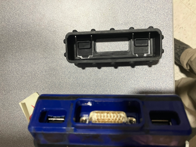
Serisouly, we're breaking it down Barny style, drop the board, which is sandwhiched together into the MDI plastic housing, notably, put the board in the "bottom" of the MDI (if we assume the top is the part with the GM wirting and logo and stuff) Then put the rubber gasket around the plastic casing in the channel, as with all the next steps, it only fits one way, if you push so hard it fits two ways, you're going to need a different instruction manual on fixing what you broke. Gently place the plastic top on and make sure the gasket seated nicely. Again, basically no pressure is needed for any of these steps, if its not fitting, stop and see why. Now you should be ready for the screws.

Step 3: Install 4x T-10 Screws
Start in one corner and torque to yeild... JOKING, just hand tight, its plastic and it doesn't need to be torqued to hard, at MOST we're looking at maybe 6 INCH pounds, or around .7Nm if you're a nerd with no friends.
To get a gold star, go in opposite corner patern like with a tire's lug nuts and then once around the circle in order to make sure they're snug, but not overly tight.
If you accidentally remove the warranty label with a heat gun and razor blade, carefully put that back by first heating the screw area and applying a tiny drop of hot glue or related easily melted plastic before putting the sticker back on,
and pressing down on the sides (not the center) evenly with something roughly the size of a 2018 Metallic Markers Medium Point by American Crafts SKU number 7-18813-62211-0 optional color 62211 Gold, or product number NOTM386675 from Amazon or your local art store
Or, you know, something similar.
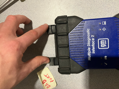
Step 4: Install peripherals & Rubber Caps
Make sure you place the Wireless Card (USB-A dongle) back in before the rubber end caps go on. Again, things only go on one way. The images below shows how to line them up in case you're doing it blind folded, but each side is a 50/50/90 chance (50/50 chance, 90% of the time you get it wrong). In order, place the Wifi dongle, the rubber caps, then screw in the DLC cable, just finger tight, I don't even have a made up torque spec for you, just not so tight that it becomes right loosey. That should be it, plug in your USB-B cable and give it another test!
Closing Note On USB Types
As a completely unrelated note, GM no longer publishes the maximum length of cables or the male end type in their recommendations (as of Sept 2024 that is) but industry standard is still sub 16 feet, USB-B to USB-A;
HOWEVER, through extensive research and testing (I just did it, and made ~100 techs do it for years), you can run a 25ft USB-B to USB-C cable no problem, the end points don't matter, the computer has literally no idea if its from USB-B or USB-A, or USB-C ect,
it does however know if you are running USB 2.0 (everything that isn't marked USB 3.x). USB 3.x does work, but
1) might send data faster than the program is expect (unliekly to ever matter, doesn't right now), or
2) may have additional pins in use (this is the real problem, if my PC thinks it can use pin 5, and pin 5 doesn't exist on the GM tool, now we have a problem).
Basically, you can always use any USB-x cable that has 4 pins (1 = VCC(+5v), 2 = Data(-), 3 = Data(+), 4 = Ground(-)), if you get into USB 3.x you can use it just fine, as long as the D(+), D(-), VCC, and Ground pins are mapped exactly as they are in USB-2, and do not connect other pins to either board.
As for the length requirement, the USB-2.0 standard says ~attenuation MAY start at greater than 5 meters (~16ft).
The problem is not data loss at 17ft (if a packet doesn't complete the CRC and handshake within the protocol, it just gets resent), it is timeout delays
or in an anolog system, the degration of signal, but get this, a USB, by definition is DIGITAL, not anology.
IE, our problem is really just, how long does it wait for a singal before saying it must not have been sent or was corrupted.
Any system, even legacy systems like 1980s vehicles or modern systems like 2025 Sierras must have a range of delay as heat, processor speed, connectivity, number of wraps in a cable, etc may have 1-2ns changes in timing.
Or, way more, as USB channels on computer vary drastically by manufacturer, computer speed, literal power (IE, on battery, low battery, plugged in, other devices in use, etc)
With new systems, after a response is sent, the standard is to wait around 5 seconds. That's a LOT of nano seconds. Hubs are bad because they just dumbly propigate out a singal, so you might get the same packet
twice if you have a short or high resistance in one section of the hub, it might be fast or slow, and the more connection points the worse
your continuity and signal strength will be.
For our technicians, USB hubs are an absolute non-starter, but cords 50ft long are fine, as long as it is one, single, braided, quality cable.
So far, no issues between 15 and 35ft. At 50ft we do have an occosional reset or retry command issued which in theory (never in practice) could cause an issue with an extremely sensitive system, again, only if its trying to force anolog data over a digital line with no error checking, no CRC,
and no god damn logic (which, GM has been know to lack at times).
Anyways, you heard it from me, a dude on the internet writing a sarcastic style blog post about a task I do daily that 100% works but a bunch of engineers from India who have never seen the device they wrote the spec for say it won't work.